 Vibration measurement, field balancing, alignment control with laser support
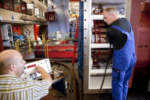
Mobile vibration sensors are here used to measure the vibration velocity and acceleration in every location of a machine. We carry out a frequency analysis. In this way we identify the fault location or the resonance location on site if there are vibration problems. This narrows down the search to determine whether an alignment error, an unbalance in the rotor or a foundation problem is causing the vibrations. This measurement setup also makes it possible to rebalance the machine rotor on site. If vibrations indicate an alignment fault, we can carry out an alignment test using a laser measurement device. This measurement data is then used to determine the alignment condition.
Roller bearing analysis, bearing condition analysis
Antifriction bearings can be examined during ongoing operation in order to detect possible defects at an early stage. This is possible with a damage frequency analysis. The BCU measurement (Bearing Control Unit) indicates any damage as early as possible. We collect all relevant data by means of sensor technology and can identify damage at an early stage. The more detailed the information about a potential fault the more accurately we can predict how long the machine should keep running. Specific damage frequencies are associated with each bearing type and the problem can be rapidly identified. We use this method to determine the time when the machine must be overhauled.
Noise measurement
This measurement is essential to determine the environmental compatibility of a machine. The measurement procedures according to which the noise levels of all stationary machines are defined are based on uniform international standards. The measured quantity for every individual measurement point is the time-averaged sound pressure level. This A-evaluation assesses the level according to the frequency-dependent human ear sensitivity. The individual measured values are locally averaged and evaluated. In this way we obtain the measurement area sound pressure level. Together with the size of the machine, the result is the internationally specified noise characteristic, the sound power level. Using this measurement, it is possible to determine whether the system noise emissions are still within the required limit values or whether additional noise-reduction measures are necessary.
Commutator true-running check
A special measuring head precisely determines the true-running of the commutator during this procedure. Smooth running, large scale concentricity deviations or small area concentricity deviations are identified. This is displayed graphically. If any defects are detected on the commutator surface, the commutator should be reworked. We can restore the commutator to mint condition if there is sufficient commutator coating available for processing. This minimises brush wear and brush sparking. This method also shows system or control faults. The test enables customers to optimally plan any standstill well in advance.
Infrared thermography
This method of diagnostics detects possible faults caused by excessive heat and indicate their source. It includes a winding analysis, identification of insulation damage, a hot spot analysis as well as a circuit fault analysis. Excessive heat development can also occur at poor interconnections or in areas of cross-section reductions. Here an increased contact resistance is made visible during operation when a current is applied. Infrared thermography can also be used, where necessary, to indicate areas with increased hysteresis losses after pyrolysis of laminated cores, for example. On the basis of these findings we determine subsequent repair steps for the laminated cores.
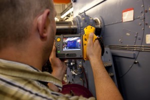
Video endoscopy
With video endoscopy components are examined for mechanical damage. As in medical application, this method can be used to examine smallest spaces. The machine does not need to be completely disassembled. We record the results for further analysis. Changes become visible if this method of diagnostics is applied on a regular basis. These changes can be classified as dangerous or harmless and repaired accordingly. A standstill can therefore be planned and the cost for a repair can be budgeted well in advance.
 Insulation resistance measurement